As I mentioned in my post about setting up a development machine I spent a fair amount of time understanding the right versions of packages and applications for my development machine. The Open Dynamic Robot Initiative has conveniently provided a couple of Dockers to support compiling and running Bolt Software. In maintaining the containerized mentality I want to understand if it was possible to build an Image that facilitates flashing of the ODRI Bolt MasterBoard, the results of this effort follow.
Ordering the Masterboard
By way of background, I ordered two assembled Masterboards by uploading three files to SEEED Studios. The lead time was about 25 days, the three files uploaded are as follows:
- Gerber Files: esp32_master_board_2020-08-26.zip
- Assembly Files: Assembly.zip
- Bill of Materials(BOM): Bill of Materials
SEEED has a minimum order quantity of five custom PCBs and a minimum assembly quantity of one. As such I received 3 PCBs and two assembled boards. I did not provide a functional test plan as I could not find one.
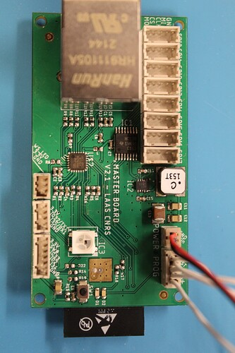
I included in my BOM the Neo Pixels as well as the Ethernet Jack, whereas ODRI ordered those separately and finished the assembly themselves. As such, my master board came ready to flash (with the exception of IC2 which I could not source until a few months after my boards were produced, the above BOM does include IC2):
Preparing the USB to Serial Adapter
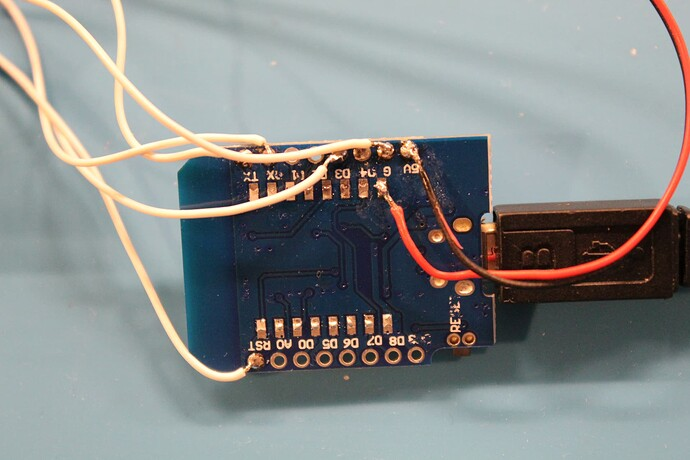
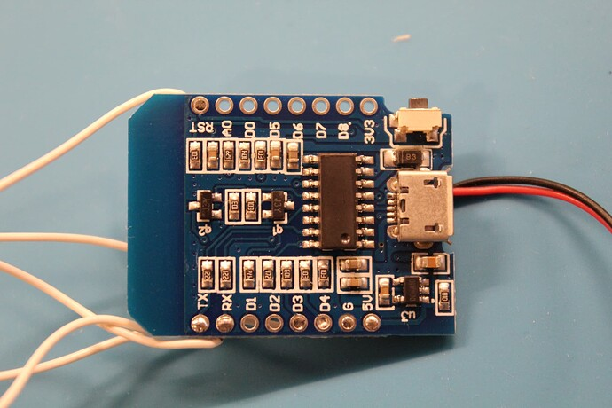
Per ODRI’s instructions in order to flash the firmware onto the ODRI Bolt MasterBoard you need a development board to act as a USB to SERIAL adapter. I purchased a low cost one from Amazon, D1 Mini DEV Board. Once received I used a hot air gun to remove the ESP8266 chip.
I then :
- Prepared five 10 cm lengths of 28 gauge wire, soldering to the respective pinouts on the D1. I ended the opposite ends of the wire in Hirose sockets to complete the PROG wire leads per the instructions.
- Purchased a DF13 two-socket pre-assembled wire for power ( as two sockets were out of stock in the U.S. at that time) from mrobotis.io (part number MRC0229-0001) WARNING POLARITY IS REVERSED, YOU NEED TO CONNECT POSITIVE TO GROUND AND GROUND TO POSITIVE!!!!!
- Connected the power cable directly to my benchtop power supply with 2A and 24V DC.
On power the D2 led should light up on the Masterboard.
Compiling the ODRI Masterboard Software
With my fresh Ubuntu 20.04 Foca installation, see ODRI Development Machine, I locally cloned the Masterboard SDK:
mkdir devel/local_master-board
cd devel/local_masterboard
git clone --recursive https://github.com/open-dynamic-robot-initiative/master-board.git
mkdir esp
cd esp
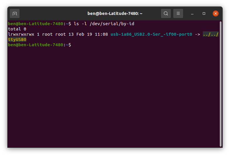
git clone -b v4.0.1 --recursive https://github.com/espressif/esp-idf.gitThen plugged in my Masterboard via my micro USB 2.0 cord and ran the following on the command line to get the serial port:
ls -l /dev/serial/by-idWhich should output something like:
Next I pulled a fresh docker image for Ubuntu 18.04 and began configuring my environment:
docker pull ubuntu:18.04

cd ~/devel #create a folder for development

docker run -it --device=/dev/ttyUSB0 -v "$(pwd)"/local_master-board:/devel ubuntu:18.04 bash  #Run and pass the local USB port and shared folder to the Contaainer
Then inside the container do some setup following this post (bold packages I added in order to support the make menuconfig command later):
apt-get update

apt-get install git wget flex bison gperf python3 python3-pip python3-setuptools cmake ninja-build ccache libffi-dev libssl-dev dfu-util libncurses5-dev libncursesw5-dev

update-alternatives --install /usr/local/bin/python python /usr/bin/python3 10
Then install esp-idf and esptool, following these instructions which have been recently updated and work well :
cd ~/../devel/esp/esp-idf
./install.sh
pip install esp-tool
Once complete, you should be able to run basic esptool commands, such as flash_id to confirm you can connect with the ESP32 chip on the Masterboard:
esptool.py --port /dev/ttyUSB0 flash_id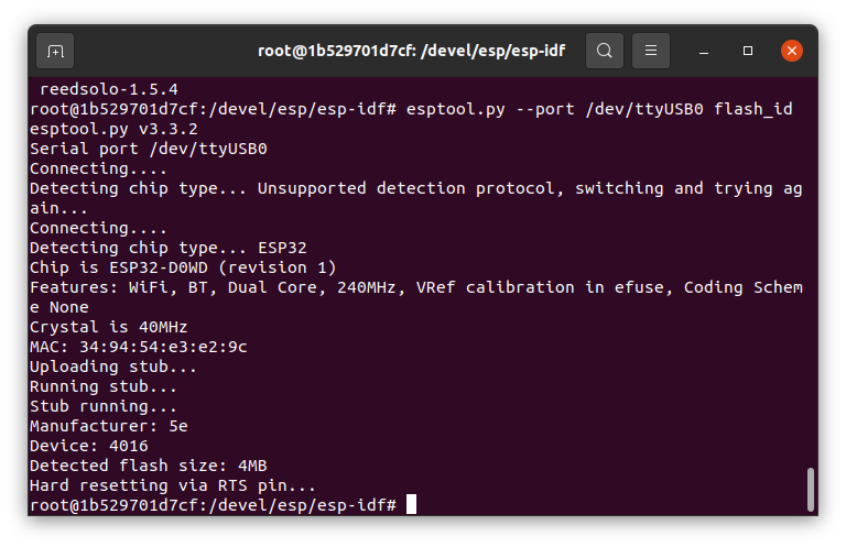
I then ran the burn fuse script per instructions and checked out the esp-idf branch that supports the ODRI Bolt MasterBoard compilation :
source export.sh
git checkout 8d1a9c0
git submodule update --init --recursive
Make sure you run export.sh before checking out the submodule, if you don’t you need to go back and check out esp-idf V4.0.1, then run source export.sh, then checkout the submodule. Now change the directory to the Masterboard firmware and flash:
cd /devel/master-board/firmware
make flash
It succeeded, and if you succeed, you should see the Neopixel LEDs start flashing red, blue, green as in the video below:
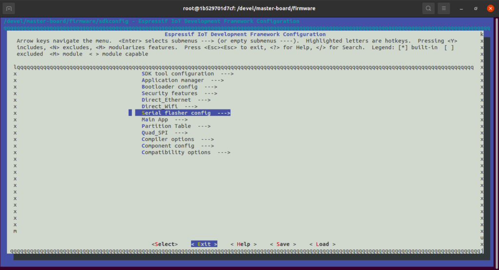
I further confirmed success by running make monitor but first, I had to configure the monitor’s baud rate to 115200 versus the default 2Mb, by running:
make menuconfigThen chose Serial Flasher:
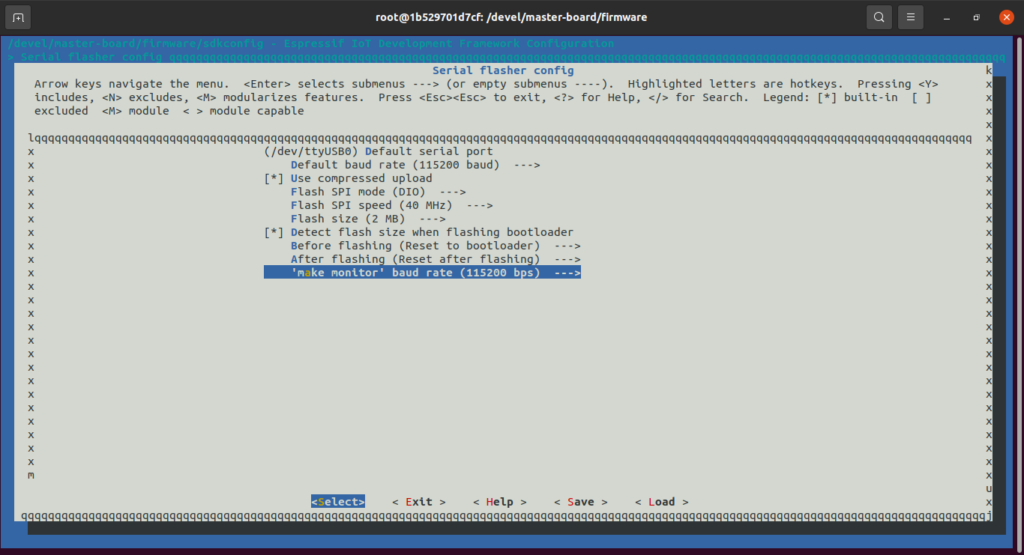
Then chose ‘make monitor’ baud rate:
Then set the baud rate at 115200:
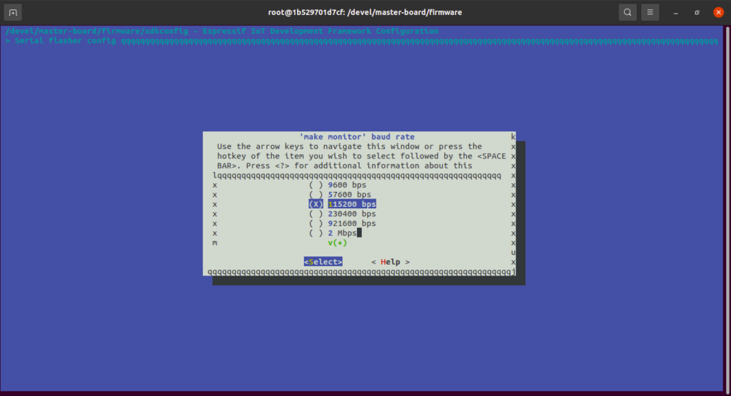
Then you should be able to run make monitor and see something like this:
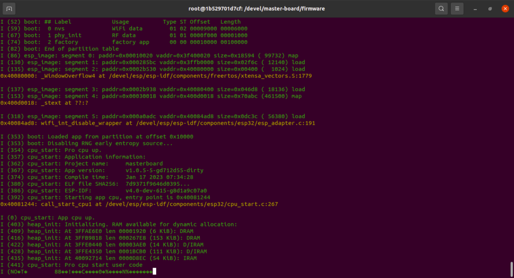
For some reason after the app cpu up, I get some garbled text, but the flash was successful
PS if you want to flash again at a later date after booting the container you need to export the path:
export IDF_PATH=~/../devel/esp/esp-idf